
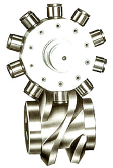
ROLLER GEAR INDEX
- Code selection table
- SRD Series
- SRS Series
- SRF Series
- SRA Series
- SRT Series
- Inquiries
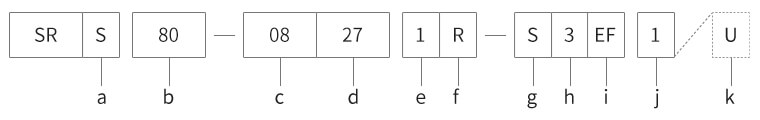
Roller Drive - CODE selection table
CODE Example of selecting code
Touch and drag the screen to confirm the contents.
| a Types of INDEX DRIVE |
Example S SHAFT TYPE |
|
|
|---|---|---|---|
| b Size of INDEX DRIVE |
Example 80 Distance between axes 80mm |
Indicate the distance between axes of input and output axes. | |
| c Number of stop |
Example 08 8 STOP |
Number of stoppage during one time of output axis. | |
| d Index angle |
Example 27 270° |
Rotating angle of input axis needed for indexing for one time. | |
| e CAM curve |
Example 1 MS curve |
|
|
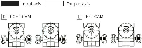
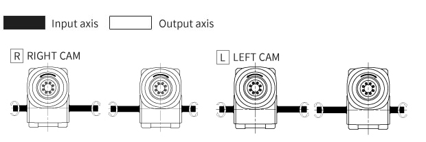
| f Rotation direction of input/output axes |
Example 1 Right CAM of 1 DEWLL |
Indicate the number of stoppage (DWELL) of output axis during one time of rotation in input axis and rotation direction of output axis on the rotation direction of input axis.
|
|
| g Specifications of output axis |
Example S Standard axis type |
|
|
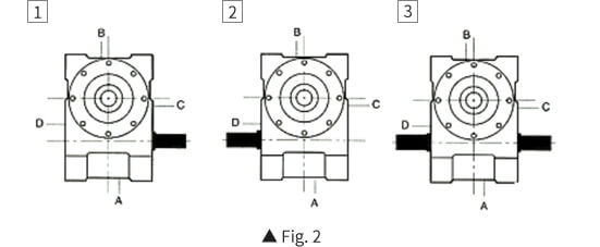
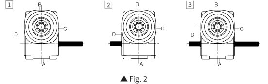
| h Specifications of input axis |
Example 3 Input axis on both sides |
Refer to the Fig. 2. |
|
| i Process side of attached hole |
Example EF Tap processing on attachment on E side and F side |
Standard specifications of attached hole of shaft type process the tap on two sides of EF. Flange type processes holes penetrating two sides of EF. If tap is needed on A, B, C, and D sides, code is added on two sides. Front processing is 'T'. |
|
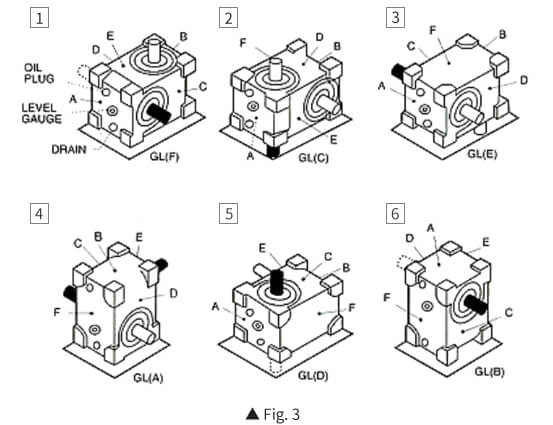
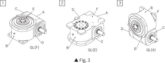
| j Attachment posture |
Example 1 Attachment posture (F side is GL) |
Refer to the Fig. 3. |
|
| k Special specifications |
Example U Special specifications |
Enter U at the end in case of special specifications of standard products (indicate catalogue).
Annex) Please attach separate specifications for special specifications. |
|
Touch and drag the screen to confirm the contents.
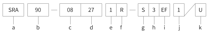
Roller Gear Index - SRA CODE selection table
CODE Example of selecting code
Touch and drag the screen to confirm the contents.
| a Type of INDEX DRIVE |
|
||
|---|---|---|---|
| b Size of INDEX DRIVE |
Example 90 Distance between axes 90mm |
Indicate the distance between axes of input and output axes. | |
| c Number of stop |
Example 08 8 STOP |
Number of stoppage during one time of output axis. | |
| d Indexing angle |
Example 27 270° |
Rotating angle of input axis needed for indexing for one time. | |
| e CAM curve |
Example 1 MS curve |
|
|
| f Direction of rotation on input and output axes |
Example R Right CAM of 1 DWELL |
Indicate the number of stoppage (DWELL) of output axis for one time of rotation on input axis and the direction of rotation of output axis on the direction of rotation in input axis.
|
|
| g Specifications of output axis |
Example S Standard axis(hollow axis), |
|
|
| h Specifications of input axis |
Example 3 Input axis on both sides |
Refer to the Fig. 2. |
|
| i Processed side of attached hole |
Example EF Tap on E side and hole processing on F side |
Standard specifications of attached hole tap E-side and process hole. |
|
| j Attachment posture |
Example 1 Attachment posture (F side is GL) |
Annex) GL (Ground line) Refer to the Fig. 3. |
|
| k Special specifications |
Example U Special specifications |
Enter U at the end in case of special specifications of standard products (indicate catalogue). * If equipping with option on standard products (torque limit and decelerator), it is regarded as a standard product.
Annex) Please attach separate specifications for special specifications. |
|
Touch and drag the screen to confirm the contents.
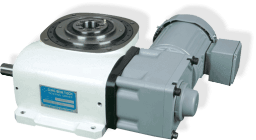
Roller Drive - SRD Series
SRD Series
SERVO DRIVES - SRD SERIES specifications
This is the index available with free setup and control of all the equal divisions to be controlled with servo motor in the use of equal speed roller gear cam.
There is no backlash on forward and backward directions that it is appropriate for determining the precise location.
Roller Gear Index - SRS Series
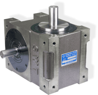
SRS Series
ROLLER GEAR INDEX - SRS SERIES specifications
Distance between axes: 45, 60, 70, 80, 110, 140, 170, 200mm
Used cam curve: Changed large size (MT), changed med-size (MS), equal changing speed (MCV), etc.
Touch and drag the screen to confirm the contents.
| Separation | Indexing angle(Deg) | |||||||
|---|---|---|---|---|---|---|---|---|
| 90 | 120 | 150 | 180 | 210 | 240 | 270 | ||
| Indexing frequency | 2 | |||||||
| 3 | ||||||||
| 4 | ||||||||
| 5 | ||||||||
| 6 | ||||||||
| 8 | ||||||||
| 10 | ||||||||
| 12 | ||||||||
| 16 | ||||||||
| 20 | ||||||||
| 24 | ||||||||
Touch and drag the screen to confirm the contents.
Roller Gear Index - SRF Series
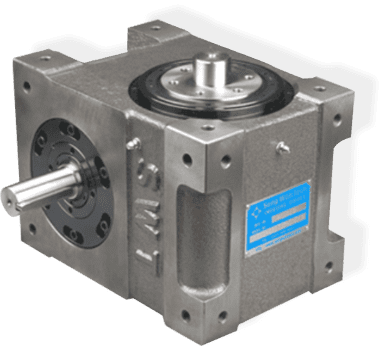
SRF Series
ROLLER GEAR INDEX - SRF SERIES specifications
Distance between axes: 45, 60, 70, 80, 110, 140, 170, 200mm
Used cam curve: Changed large size (MT), changed med-size (MS), equal changing speed (MCV), etc.
Touch and drag the screen to confirm the contents.
| Separation | Indexing angle(Deg) | |||||||
|---|---|---|---|---|---|---|---|---|
| 90 | 120 | 150 | 180 | 210 | 240 | 270 | ||
| Indexing frequency | 2 | |||||||
| 3 | ||||||||
| 4 | ||||||||
| 5 | ||||||||
| 6 | ||||||||
| 8 | ||||||||
| 10 | ||||||||
| 12 | ||||||||
| 16 | ||||||||
| 20 | ||||||||
| 24 | ||||||||
Touch and drag the screen to confirm the contents.
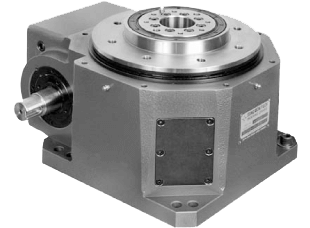
Roller Gear Index - SRA Series
SRA Series
ROLLER GEAR INDEX - SRA SERIES specifications
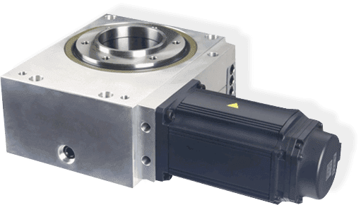
Flange side of output axis is wide and is with hollow anchored axis that it is convenient to wire oil pressure or pneumatic wiring in stable manner.
Touch and drag the screen to confirm the contents.
| Separation | Indexing angle(Deg) | |||||||||
|---|---|---|---|---|---|---|---|---|---|---|
| 90 | 120 | 150 | 180 | 210 | 240 | 270 | 300 | 330 | ||
| Indexing frequency | 2 | |||||||||
| 3 | ||||||||||
| 4 | ||||||||||
| 5 | ||||||||||
| 6 | ||||||||||
| 8 | ||||||||||
| 10 | ||||||||||
| 12 | ||||||||||
| 16 | ||||||||||
| 20 | ||||||||||
| 24 | ||||||||||
| 32 | ||||||||||
Touch and drag the screen to confirm the contents.
Roller Gear Index - SRT Series
SRT Series
ROLLER GEAR INDEX - SRT SERIES specifications
Flange side of output axis is wide and is with hollow anchored axis that it is convenient to wire oil pressure or pneumatic wiring in stable manner.
Touch and drag the screen to confirm the contents.
| Separation | Indexing angle(Deg) | |||||||||
|---|---|---|---|---|---|---|---|---|---|---|
| 90 | 120 | 150 | 180 | 210 | 240 | 270 | 300 | 330 | ||
| Indexing frequency | 4 | |||||||||
| 5 | ||||||||||
| 6 | ||||||||||
| 8 | ||||||||||
| 10 | ||||||||||
| 12 | ||||||||||
| 15 | ||||||||||
| 16 | ||||||||||
| 20 | ||||||||||
| 24 | ||||||||||
Touch and drag the screen to confirm the contents.
Roller Gear Index - Inquiries of manufacturing
Inquiries of manufacturing
Please enter the empty areas below for selection of index model and our company will calculate torque to select model and provide the estimates and approved drawing.